
Hi 👋
In this article, I explain in detail what an SFU server is and everything related to it. The topic can be quite complex to grasp, so before diving into the terminology, I recommend going through the 7 step visualization below! I promise that if you picture everything in detail, this topic will feel very simple and clear!
Visualization
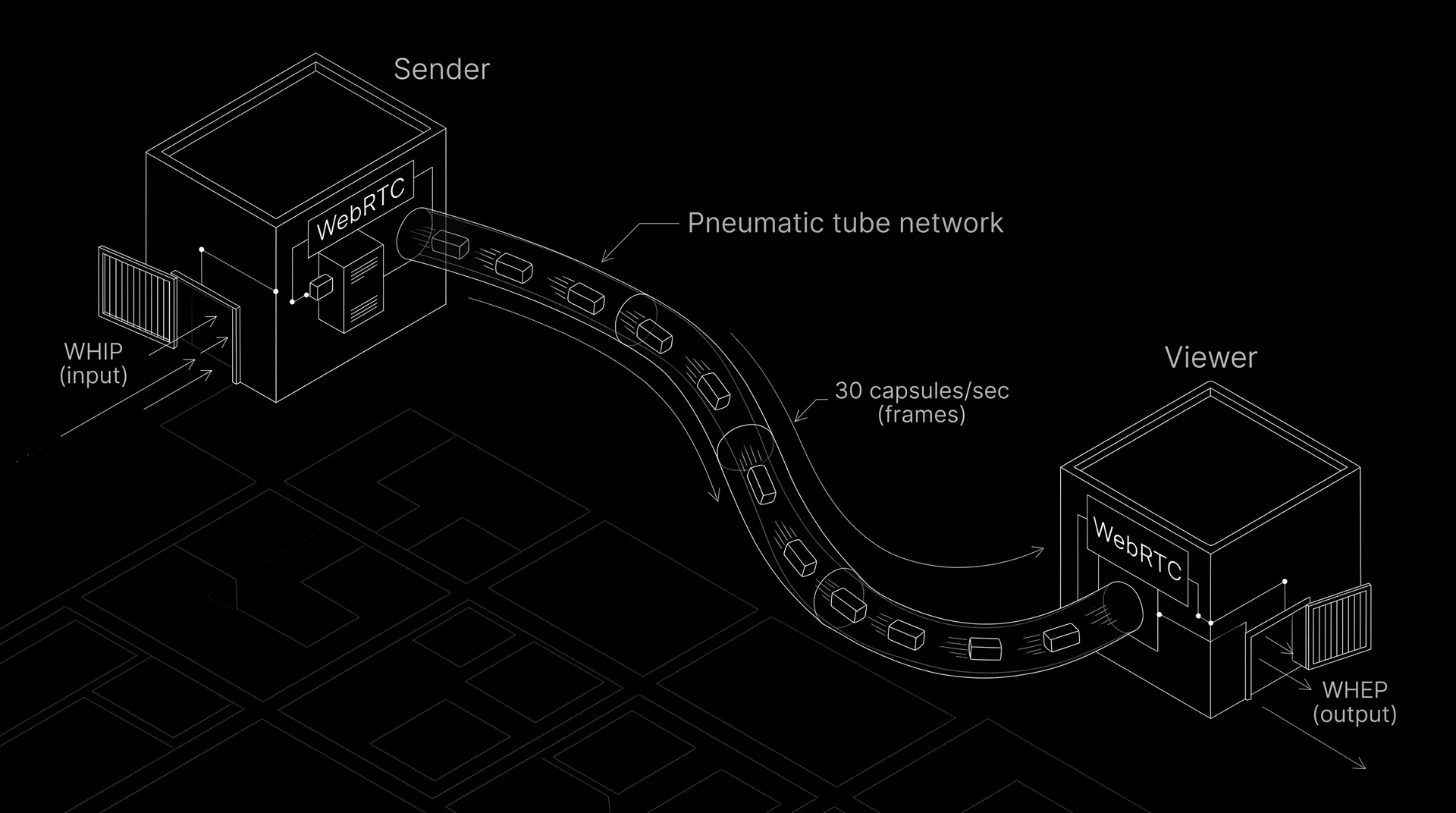
Imagine in 3D space a high speed pneumatic tube system (a network of transparent tubes with capsules) running between two buildings across an entire city. The whole system solves one physical task: every second, it transports 30 three dimensional frame casts from the Sender's room to the Viewer's room if we are talking about 30fps so fast that at the other end they blend into live motion.
The machinery built directly into the walls of both buildings that handles sending and receiving these capsules without external gear - is WebRTC (and the simple cargo gates on the sides for connecting external studio cameras and television screens with a single request - are WHIP for input and WHEP for output).
Now let's move our 3D camera along the tube from the first millimeter to the last, following a strict "Problem → Solution" chain.
Step 1. Why a frame cannot be sent through the tube whole (RTP and SRTP)
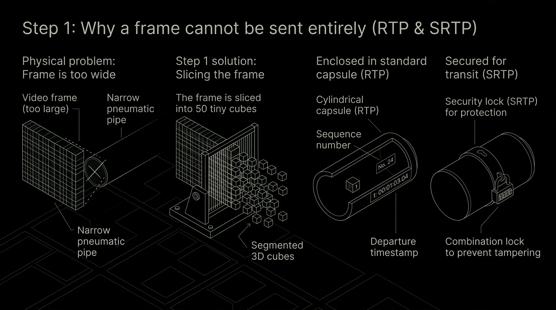
Physical problem: A single crisp video frame cast weighs too much - it is simply wider than the diameter of a standard city tube and will not fit through it in one piece.
Solution in 3D space: At the start, a machine slices each frame into 50 small numbered cubes.
- Each cube is placed into a standard cylindrical RTP capsule with a sequence number and exact departure timestamp stamped on its casing (so the cubes can be reassembled in the right order on the viewer's side).
- On the outside, for the duration of its flight through the street tube, the capsule is locked with an SRTP travel combination lock so no one on the street can swap out the cube.
Step 2. Why there is a switch in the city center instead of a reassembly plant (MCU vs. SFU)
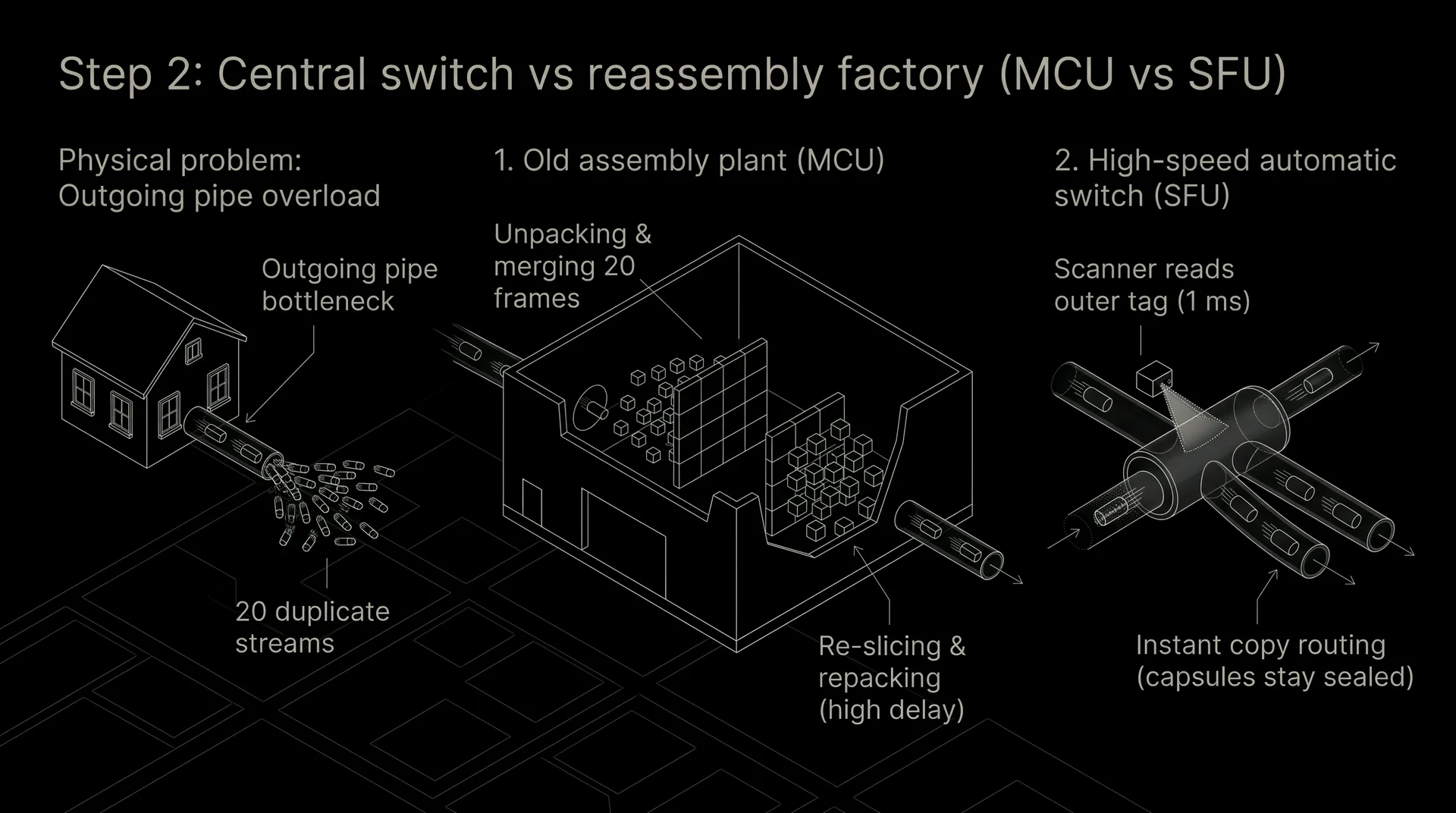
Physical problem: When 20 people join a call, your home machine cannot fire 20 identical sets of capsules to each participant individually - your outgoing tube from home would choke instantly. That means you need to send a single stream of capsules to a central hub in the city that will duplicate them for everyone else.
Two generations of this hub in 3D:
- The old assembly plant (MCU): Capsules from all 20 people flew into a large hall. Workers opened every capsule, took out all the cubes, glued the 20 faces into a single composite panel, sawed it back into cubes, and repacked them into capsules for each viewer. This took precious fractions of a second and required a massive facility.
- The high speed automated switch (SFU): A modern hub - is a compact transparent junction where capsules containing casts are never opened at all. A capsule from you flies into the SFU junction at full speed, a sensor reads only the address tag on the outside in a millisecond, and an automated switch instantly fires copies of that capsule into the viewers' tubes.
Step 3. The switch cannot shrink the cargo, and the elevator tube is narrow (Simulcast and SVC)
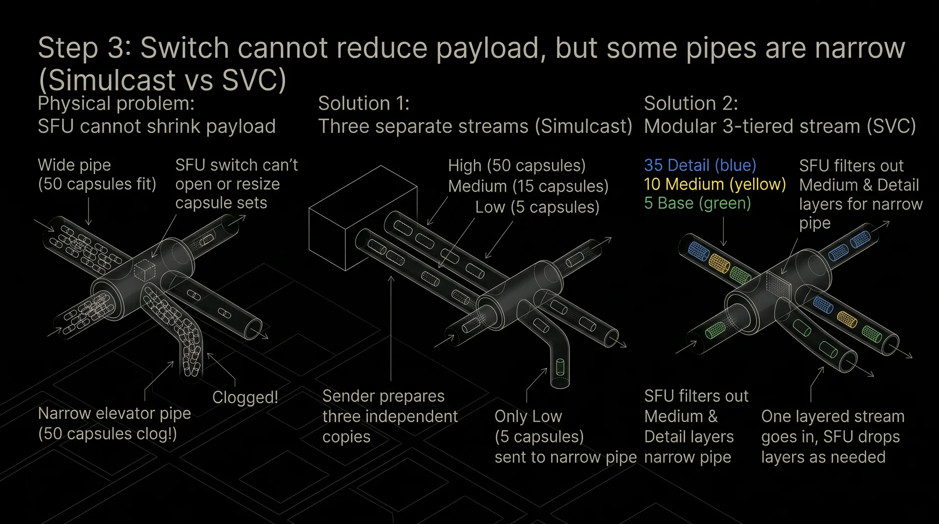
Physical problem: Abandoning the assembly plant in favor of the fast SFU switch immediately created a new bottleneck. Two different tubes exit the SFU junction: a wide highway (home fiber internet) goes to the first viewer, easily fitting all 50 capsules of a frame, while a narrow tube running into an elevator shaft goes to the second viewer, where at most 5 capsules can squeeze through at a time. Because the SFU switch does not open capsules and cannot saw the cubes down to fit the narrow tube, trying to push 50 capsules in there will jam the neck completely.
Solution in 3D space: A reduced set of cubes must be prepared by the sender right at home before departure:
- Method 1 - Three separate queues (Simulcast): The sender's machine at home creates three independent copies of the same frame at once - large (50 capsules), medium (15 capsules), and small (5 capsules) - and sends all three streams to the SFU junction. The switch at the station simply routes the large stream into the wide tube, and the small one - into the narrow elevator tube.
- Method 2 - Three color modular kit (SVC): To avoid sending three separate copies from home to the station and wasting tube space, the sender transmits a single set of capsules split by color:
- 5 green capsules carry the base outline of the frame (enough to assemble a low-resolution picture);
- 10 yellow capsules add medium sharpness on top of the base outline;
- 35 blue capsules add fine high-definition details. Now, when the viewer's tube in the elevator narrows, the SFU switch cuts off the blue and yellow capsules with a single flap movement, letting only the 5 green ones into the narrow tube!
Step 4. How the switch in the city center knows that a tube in an elevator 50 km away is starting to clog (TWCC, GCC, BWE)
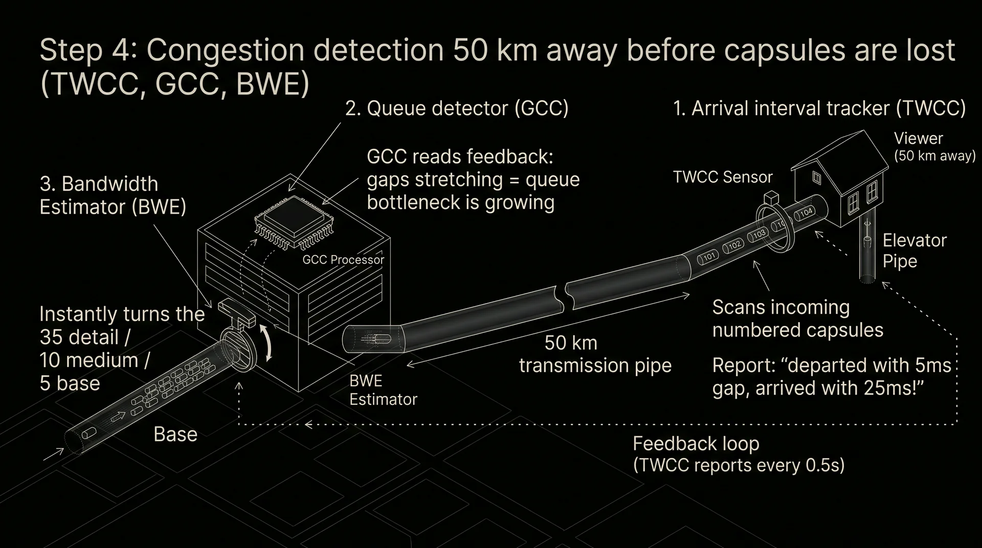
Physical problem: The automated SFU switch sits in a data center, while the bottleneck occurs on the very last leg - right before entering the viewer's phone in the elevator. If you wait until the narrow tube overflows and capsules start smashing and getting lost, the picture on the viewer's screen will already freeze (since the frame cannot be assembled without the lost cubes). The switch must learn about the narrowing tube before even a single capsule is lost.
Solution in 3D space: Along the tube from the SFU junction to the viewer, a closed measurement loop of three linked instruments is installed:
- Finish line interval counter (TWCC): Upon leaving the SFU junction, every capsule is stamped with a continuous sequence number (1, 2, 3...). Right before the entrance to the viewer's phone sits an optical ring with a stopwatch. It records the exact arrival time of each capsule and every half second sends a brief TWCC report back to the station: "Capsules #101, 102, and 103 left the station 5 milliseconds apart, but arrived at my finish line stretched out to 25 milliseconds apart!"
- Queue build up sensor (GCC): The GCC computing unit at the SFU station reads this report and sees simple mechanics: if the time gap between capsules at the exit has grown, they have started slowing down in a queue before the narrow bottleneck of a router or cell tower. The capsules are still intact, but congestion in the tube is already growing.
- Bandwidth valve (BWE): Receiving the signal from the GCC sensor, the BWE regulator calculates the actual diameter of the tube at that exact second and immediately turns the flap on the SFU switch: "Throughput dropped - cut off the blue and yellow SVC layers, feed only the green base layer into the tube!"
Step 5. How to hide the cubes from the SFU station itself without blinding the switch (Insertable Streams and MLS)
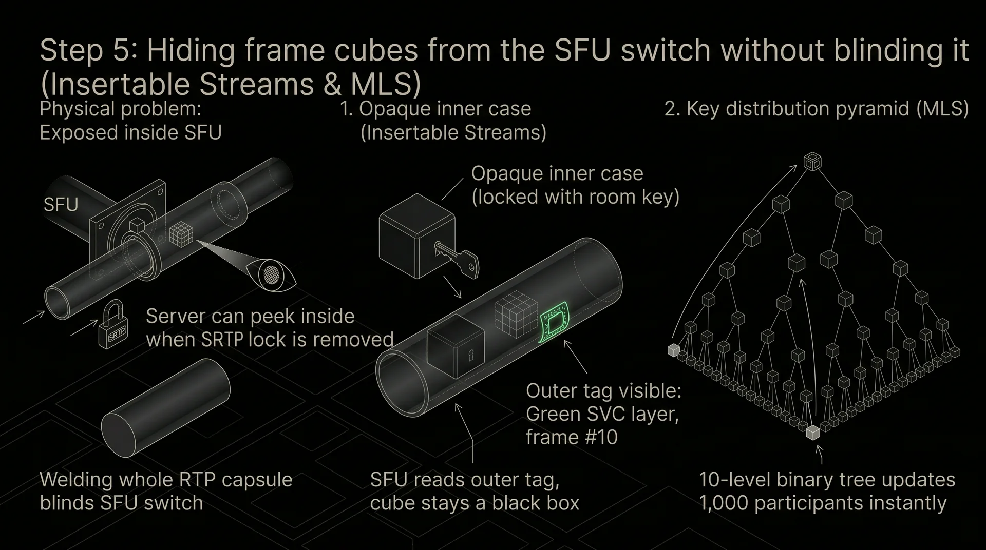
Physical problem: Recall Step 2: the street lock SRTP secures the capsule only on the way from home to the SFU junction. At the junction itself, this street lock is removed so the automated system can read the capsule's color, rewrite the number for a specific viewer, and attach a new street lock. However, this means that inside the SFU junction itself, the frame cubes are exposed for a fraction of a second (the server owner could peek inside). Yet if you weld the entire RTP capsule shut back at home, the SFU switch won't see which layer is the green base and which is blue, and will stop working.
Solution in 3D space:
- Internal opaque case (Insertable Streams): Right in the sender's room, before the frame cube drops into the transparent RTP capsule, a side mechanism seals the cube itself inside an opaque internal case locked with the private key of the room's participants. Meanwhile, an open colored label remains on the outside wall of the RTP capsule itself ("Green SVC layer, frame #10"). Now the SFU switch clearly sees the colored label and cuts off extra layers for the elevator, while the cube inside the case remains a black box to the station.
- Key distribution pyramid (MLS): So that 1,000 people in a call share the same key to this internal case and have it change instantly whenever anyone leaves (otherwise the person who left could read others' capsules), participants are linked into a pyramid of pairs (by 2, by 4, by 8 people). When one person leaves the room, the new key is passed up through just 10 levels of the pyramid from bottom to top instead of cycling through all 1,000 participants one by one.
Step 6. Fourth consequence: How to route a tube out of your gated courtyard and pass street checkpoints (STUN, TURN, DPI, ICE, Happy Eyeballs)
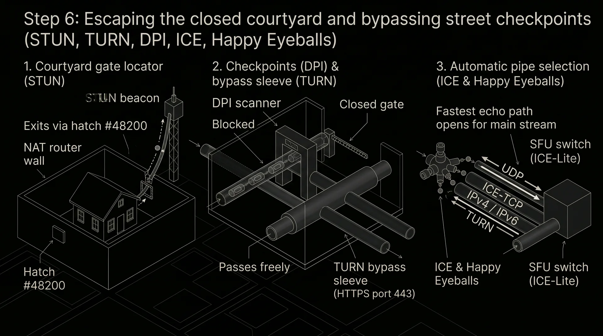
Physical problem: Before capsules can even reach the city SFU junction, they have to get out of the sender's building. And the building sits inside a closed courtyard behind the solid fence of a home router (NAT), plus ISP inspection checkpoints stand on the city streets.
Solution in 3D space:
- External courtyard gate sign (STUN): Sitting inside the courtyard behind the router's fence, your machine only knows its internal apartment number, and cannot see which external hatch in the courtyard wall its tube exits through onto the street. The machine fires a test ball to a street STUN beacon, which sends back a reply: "Your tube exits onto the street through external hatch #48200".
- Inspection checkpoints (DPI) and the bypass sleeve (TURN): On some streets stand ISP DPI scanners that X-ray the tubes and slam the valve shut as soon as they spot RTP capsules inside. And in strict office buildings, direct hatches to the street are welded shut altogether. In those cases, capsules are routed through a TURN bypass transit hub inside the standard opaque shell of a regular website (HTTPS on port 443). The DPI scanner sees standard banking traffic and lets it through nonstop.
- Automatic working tube selection (ICE and Happy Eyeballs): Between home and the SFU station there are always several routing options: a direct overhead tube (UDP), a ground rail tube (ICE-TCP), an old IPv4 bridge, a new IPv6 bridge, and a TURN bypass sleeve. The ICE dispatcher gathers a list of all available hatches (in Trickle ICE mode it tests the very first hatch immediately without waiting for the rest, while the SFU station itself in ICE-Lite mode simply waits for incoming balls at its fixed address). So the user does not have to wait for each bridge to be tested one after another, the Happy Eyeballs starter valve fires test balls into parallel tubes simultaneously: whichever tube returns an echo first within hundredths of a second - opens immediately for the main stream.
Step 7. Finale: Why for 1,000,000 viewers a single tube is replaced with a multi barrel cylinder and district warehouses (QUIC and MoQ)
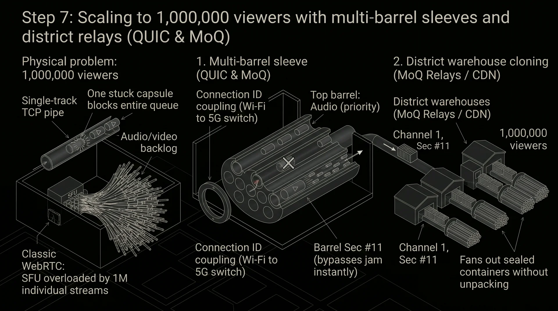
Physical problem: The entire pneumatic line we built (WebRTC + SFU) runs with minimal latency while there are 10, 50, or 500 people in the room. But what happens if 1,000,000 viewers tune into a live broadcast?
- If you route a million people through an old single track tube (TCP), where all capsules are linked into one rigid queue, the very first stuck video capsule will block the entire tube behind it, audio included.
- And if you try to distribute a million streams via classic WebRTC (RTP over UDP), the SFU junction will have to turn a million individual speed valves and re encrypt every capsule personally for each viewer - because standard city warehouses (CDNs) do not know how to copy an unnamed RTP stream.
Solution in 3D space - Multi barrel QUIC sleeve and MoQ container distribution:
- Hose with dozens of independent inner barrels (QUIC): Instead of a single tube between the server and viewer, a wide protected QUIC sleeve is laid. At its end sits a floating coupling (Connection ID): when a person leaves home and switches from Wi-Fi to 5G, the coupling snaps onto the new tube in a millisecond without stopping the stream. And inside the sleeve itself, like in a revolver cylinder, run dozens of separate smooth barrels. If a capsule gets stuck in one barrel, cargo keeps flying through all the neighboring barrels inside the same sleeve without the slightest hitch.
- A dedicated barrel for every second of video (MoQ): The MoQ dispatcher distributes the media stream across these internal QUIC barrels following three simple rules:
- Top barrel audio only: voice capsules always fly out first, bypassing any video queues.
- Every new second of video is loaded into its own adjacent barrel! At the front of the barrel goes a heavy starter capsule (the full keyframe for that second), followed down the same barrel by 30 lightweight motion capsules for that second.
- Overtaking a jam without waiting: if a viewer steps into an elevator and a capsule gets stuck in Barrel #10 (for the 10th second), the system does not wait for it to be pushed through! In that exact fraction of a second, a fresh starter capsule for the new second is fired down the neighboring Barrel #11, bypassing the jam, while the stuck 10th barrel is simply shut off and discarded.
- Duplication through standard city warehouses (MoQ Relays / CDN): Because each one second magazine in MoQ has clear serial markings on the outside ("Channel 1, Video, Second #11"), the central SFU station no longer needs to run a million tubes to viewers. It sends just one magazine to ordinary district warehouses along the route (CDN servers), and those, without ever opening the encrypted capsules, simply clone the ready made one second magazines from their shelves into hundreds of thousands of local viewers' QUIC sleeves.
Glossary of Terms and Standards
WebRTC (Web Real Time Communication)
An open stack of protocols and browser interfaces (APIs) for direct transmission of audio, video, and arbitrary data without installing third party plugins. The project was launched by Google in May 2011 (built upon acquired and open sourced technologies from GIPS and On2 Technologies), and in January 2021 the W3C consortium and IETF engineering board approved it as the official WebRTC 1.0 standard. It was created so that any browser and mobile application could establish secure audio and video communication.
MCU (Multipoint Control Unit)
First generation server architecture for group video conferencing where the server decodes video from all participants, stitches them into a single composite image, and re encodes it for each viewer. It emerged in the 1990s within ITU T telecommunication standards, first in the H.320 family (1990–1993, video conferencing over digital ISDN lines, specifications H.231/H.243) with contributions from PictureTel and Tandberg, and from 1996 onward - in the H.323 standard for IP networks. It was created because weak processors and narrow communication channels on endpoint devices at the time could not physically receive and decode more than one video stream simultaneously.
SFU (Selective Forwarding Unit)
the architecture of a modern media server that receives encrypted packets from participants and forwards selected copies to other viewers without decoding or recompressing the video. This approach was first implemented in a commercial product by Vidyo in 2008 (based on the H.264 SVC codec), while the term SFU itself became established in IETF documents and the open source Jitsi VideoBridge project between 2012 and 2015. It was created to relieve servers from heavy video transcoding, reduce latency to tens of milliseconds, and lower the cost of serving thousands of rooms.
RTP and SRTP (Real time Transport Protocol / Secure RTP)
the core network format for packaging audio and video frames with timestamps and sequence numbers. RTP was developed by an IETF working group led by Henning Schulzrinne (RFC 1889 in 1996, updated in RFC 3550 in 2003), and the SRTP encryption extension was created by Cisco and Ericsson engineers in 2004 (RFC 3711). They were created for fast delivery of media streams over UDP with protection against eavesdropping and packet tampering.
Simulcast (Simultaneous Broadcast) - a technology where the sender's device simultaneously compresses and sends two or three independent copies of camera video at different resolutions (for example, 1080p, 540p, and 270p) to the server. It was introduced into WebRTC by Google, Cisco, and Mozilla in the mid-2010s and officially standardized by the IETF in January 2021 (RFC 8853). It enables an SFU server to deliver a stream matching each viewer's internet capacity without transcoding the picture on the server itself.
SVC (Scalable Video Coding)
a technology for encoding video into a single stream divided into dependent layers a low quality base layer and additional layers for spatial detail and frame rate. The H.264/SVC standard was adopted by ITU T and ISO/IEC in 2007, and between 2013 and 2019 Google and the Alliance for Open Media (AOMedia) built it into the VP9 and AV1 codecs (W3C WebRTC SVC specification). It was created for flexible quality adaptation on the server by stripping upper layers while consuming less upstream bandwidth than Simulcast.
BWE (Bandwidth Estimation)
a module inside the media server and browser that calculates the maximum safe data transfer rate for each connection in real time. It has been actively developed within the WebRTC project since 2011 by Google and IETF engineers. It was created so that video calls can adapt ahead of time to drops in mobile or home network quality without pushing the connection to packet loss and frozen video.
TWCC (Transport Wide Congestion Control)
a feedback mechanism where the sender attaches a continuous sequence number to every outgoing RTP packet, and the receiver returns compact receipts with the exact arrival time of each packet. It was developed by Google engineers (Stefan Holmer and colleagues) in 2015 for the IETF RMCAT working group to replace the older REMB mechanism. It was created to move bandwidth calculation math from the receiving side to the sending side (Send side BWE on the server when distributing streams to viewers, and in the client browser when sending camera video) and to spot the slightest queue growth in routers immediately.
GCC (Google Congestion Control)
a mathematical video bitrate control algorithm combining inter packet delay variation analysis with packet loss percentage. It was proposed by Google between 2012 and 2016 in the IETF RMCAT working group (draft ietf rmcat gcc). It was created to maintain minimal latency in a call so that the video stream does not clog router buffers or crowd out other traffic on the user's network.
STUN (Session Traversal Utilities for NAT)
a lightweight protocol that allows a device behind a home router to discover its external public IP address and port. It was developed by Jonathan Rosenberg (Dynamicsoft / Cisco) and adopted by the IETF in 2003 (RFC 3489, updated in RFC 5389 in 2008 and RFC 8489 in 2020). It was created so that two endpoints on the internet can discover each other's external addresses and establish a direct connection.
TURN (Traversal Using Relays around NAT)
a protocol for forcibly relaying media traffic through a public intermediary server when a direct connection is blocked by a strict firewall or symmetric NAT. It was developed by Jonathan Rosenberg, Rohan Mahy, and Philip Matthews and approved by the IETF in 2010 (RFC 5766, updated in RFC 8656 in 2020). It was created as a fail safe fallback transport for restrictive corporate and mobile networks.
ICE, ICE Lite, Trickle ICE, and ICE TCP
a family of protocols for automatically gathering all possible network addresses (candidates) and testing routes between a client and a server. The core standard was adopted by the IETF in 2010 (RFC 5245, updated in RFC 8445 in 2018), the extension for running over TCP was released in 2012 (RFC 6544), and the accelerated Trickle ICE mode was officially published in January 2021 (RFC 8838). It was created so the application can automatically find the fastest and shortest working path for a call.
DPI (Deep Packet Inspection)
a network traffic inspection technology on ISP equipment and corporate gateways that analyzes not only IP addresses and ports, but also the internal structure and signatures of protocols. It has been widely deployed since the mid 2000s by telecom vendors (Cisco, Sandvine, Huawei). Initially built to protect corporate networks and prioritize traffic, it is also used to throttle or block voice and video protocols.
Insertable Streams (WebRTC Encoded Transform)
a browser programming interface (API) that gives developers access to compressed video and audio frames right before they are packaged into network packets. It was designed by Google and Apple engineers in the W3C WebRTC working group in 2020. It was created primarily to implement end to end encryption (E2EE) in group browser calls through an SFU, as well as to attach custom metadata to frames.
MLS (Messaging Layer Security)
a cryptographic protocol for managing group encryption keys based on binary trees. It was developed by an IETF working group with participation from Mozilla, Cisco, Cloudflare, Wire, and the University of Oxford, and officially approved as RFC 9420 in July 2023. It was created so that thousands of conference participants can securely rotate shared encryption keys in milliseconds whenever someone joins or leaves the room.
WHIP and WHEP (WebRTC HTTP Ingestion / Egress Protocol)
standards for quickly starting a broadcast into a server (WHIP) and pulling a stream as a viewer (WHEP) using a single standard HTTP POST request. They were created by Sergio Garcia Murillo (Millicast / Dolby) and Alex Gouaillard in the IETF WISH working group between 2021 and 2025 (WHIP was officially adopted as RFC 9725 in 2025, and WHEP is its paired IETF specification). They were created to eliminate incompatibility between different video servers and replace the legacy RTMP protocol in software like OBS Studio.
QUIC (Quick UDP Internet Connections)
a next generation transport protocol running over UDP that combines connection setup with TLS 1.3 encryption and independent data streams. It was created by Jim Roskind at Google in 2012 and approved by the IETF in May 2021 as RFC 9000 (the foundation of HTTP/3). It was designed to speed up connections, seamlessly switch between Wi Fi and mobile networks, and eliminate the head of line packet blocking inherent to the older TCP protocol.
MoQ (Media over QUIC)
a unified protocol for publishing and delivering live video and audio over the QUIC transport. It has been developed by the IETF MOQ working group since 2022 by engineers from Meta, Cisco, Cloudflare, Google, and Twitch. It was created to combine WebRTC's interactive sub second latency with inexpensive scaling across millions of viewers via standard caching CDN servers.
Happy Eyeballs (Fast Fallback)
a parallel network path probing mechanism where an application initiates connections across different routes and picks whichever responds first. Originally developed by Dan Wing and Andrew Yourtchenko at Cisco and standardized by the IETF in 2012 (RFC 6555, updated in RFC 8305 in 2017) to race IPv6 and IPv4 addresses in parallel so broken ISP IPv6 routing would not hang website loading. Later, this same principle became the foundation for ICE Dual Stack Fairness (RFC 8421), HTTP/3 (RFC 9114), and Happy Eyeballs v3 for seamless racing between UDP (QUIC/WebRTC) and TCP protocols.
Why You Need an SFU
When two people make a video call, their devices can send video and audio directly to each other. But as soon as five, twenty, or a thousand participants enter a room, direct peer to peer mesh communication turns into a web each participant's phone is forced to compress and send dozens of outgoing streams at once, instantly saturating their internet link and draining their battery. To solve this problem, a dedicated SFU server is placed in the center of the room.
Older video servers operated on the MCU principle they received video from all participants, fully decoded every picture into raw pixels, stitched them into a single shared grid, and re encoded the video for each viewer. That approach required massive computing power and expensive server CPUs or GPUs, while adding extra latency from double transcoding.
SFU architecture works on a fundamentally different principle the server does not decode or recompress the picture at all. It acts as a high speed network dispatcher (packet switch) receiving ready made encrypted audio and video fragments from one person and instantly forwarding copies of them to the other participants in the room. By eliminating heavy image processing, a single server can handle thousands of video streams simultaneously.
How the Server Processes Hundreds of Thousands of Packets per Second
Hundreds of thousands of small network packets (1,000–1,200 bytes each) pass through an SFU every second. If you write such a server like an ordinary website, the operating system will spend all its CPU resources on context switching and waiting in queues rather than forwarding video. Therefore, three low level mechanisms operate inside a high performance SFU.
1. Asynchronous Batching I/O
A typical program makes a separate system call to the operating system kernel (recvmsg or sendmsg) for every single network packet. Each call requires switching the CPU from unprivileged User Space into privileged Kernel Space and back, burning hundreds of processor cycles.
2. Lock Free Architecture
In multithreaded programs, the main performance bottleneck - is contention for shared memory. If multiple CPU threads simultaneously try to write data to a shared list of room participants, they have to acquire a lock. While one thread modifies the data, the remaining threads are put to sleep by the OS scheduler and sit idle in a queue. At a rate of 500,000 packets per second, locks (mutexes) paralyze the server immediately.
Under the hood, media servers solve this problem in two ways
- Worker process isolation A completely independent worker process or thread (Worker) runs on each CPU core with its own event loop and its own routing table. In stateless relays (for example, in high load TURN servers), threads can share a single port via the Linux kernel option SO_REUSEPORT, where the network card distributes packets across cores by hashing addresses and ports (5 tuple). Meanwhile, in servers like Mediasoup, where a specific room (Router) strictly lives inside one specific Worker process, each worker process listens on its own dedicated port (WebRtcServer), or an eBPF filter (SO_ATTACH_REUSEPORT_EBPF) is placed in front of them to route packets straight to the right core based on the session identifier (ice ufrag). Threads share no memory with each other, so they need no mutexes.
- Lock free ring buffers If one thread still needs to pass a packet to another (for instance, when the sender and viewer are served by different cores), an in memory ring queue is used. For a "single producer - single consumer" pair, no locks are needed at all one thread modifies only the write index, and the other - only the read index using fast atomic operations and memory barriers (Acquire / Release) in just a few CPU cycles. And if multiple threads write to the queue at once (MPSC / MPMC), pointers are advanced via hardware atomic compare and swap instructions (CAS - Compare And Swap, taking 15–40 cycles) without system calls or stopping threads.
3. Strict CPU Core Pinning (CPU Affinity)
By default, the operating system task scheduler constantly migrates program worker threads from one CPU core to another to balance the load evenly. For a real time media server, this thread migration across cores is highly detrimental for three reasons
- Loss of hot L1 and L2 cache Every physical CPU core has its own ultra-fast memory - L1 and L2 cache (access time around 1–4 nanoseconds versus 60–100 nanoseconds for main RAM). While a thread runs on a single core, the RTP packet processing code and SRTP encryption contexts sit right inside the L1/L2 cache. As soon as the thread migrates to a neighboring core, its cache there is empty, and the processor stalls for hundreds of cycles fetching data from slow main memory (Cache Miss).
- Cold address translation buffer On the new physical core, the cache that translates virtual memory addresses to physical ones (TLB) lacks entries for that thread's memory pages, triggering a series of expensive TLB Miss penalties when accessing network buffers.
- NUMA architecture penalties On multi socket servers, migrating a thread to a core on a different CPU socket forces it to pull network buffers from remote memory across the inter processor interconnect at higher latency.
To eliminate this, at startup the SFU calls the system function sched_setaffinity() (or pthread_setaffinity_np) and strictly pins each worker thread to a specific physical CPU core (for example Thread #1 - only on Core #1). As a result, instructions and network buffers stay spinning in the hot L1/L2 cache of their dedicated core, boosting server throughput by 30–50%.
What Happens to Video in an Elevator and How BWE, TWCC, and GCC Work
A single call often brings together people with very different internet connections one is sitting at home on gigabit fiber, while another is riding in an elevator with weak cellular reception. If the server blindly tries to send a heavy high definition picture (3 Mbps) to the person in the elevator whose link has dropped to 100 Kbps, the video on their screen will freeze on a still frame (even though the smartphone itself hasn't hung, and the other person's voice continues to come through).
Physically and in software, this video freeze unfolds along a chain of events
- Splitting a frame into dozens of packets A single 1080p video frame (especially a full keyframe - I frame) weighs between 30 and 100 KB. Since the maximum size of a single network packet on the internet (MTU) is around 1,200–1,500 bytes, one video frame is sliced into 30–80 separate RTP packets.
- Cell tower buffer overflow and packet drops When a burst of dozens of packets hits the narrow bottleneck of the radio link in the elevator, the memory queue at the base station overflows in a fraction of a second (Bufferbloat), and the carrier's router starts forcibly dropping packets that do not fit (Packet Loss).
- Decoder stall and retransmission storm (PLI Storm) The video decoder in the phone cannot assemble a frame if even a few of its 50 packets are lost. Moreover, the delta frames (P frames) following a keyframe store only mathematical changes relative to the previous frame. Having lost its reference point, the decoder leaves the last intact image on screen and sends an emergency PLI (Picture Loss Indication) signal to the server - "send a new full keyframe". If the server responds by sending a new heavy keyframe into the elevator, it will clog the narrow channel for good.
To keep the network from reaching packet loss and frozen frames, WebRTC runs a continuous bandwidth estimation system called BWE (Bandwidth Estimation) powered by the TWCC feedback protocol and the GCC algorithm. When video travels from the server to the viewer (Downlink), the SFU server calculates the speed, and when video travels from the client's camera to the server (Uplink) - the exact same algorithm runs inside the sender's browser.
How the TWCC Data Collection Protocol Works
- Continuous outbound numbering The sender (for example, the SFU when distributing a stream to a viewer) adds a special header extension to every outgoing RTP packet - a single monotonically increasing packet number (Transport Wide Sequence Number 1, 2, 3, 4...), and records the exact departure time of each number in its own memory with microsecond precision.
- Arrival log on the phone The recipient's smartphone receives these packets and logs the exact arrival time of each number according to its internal clock.
- Feedback receipt Every 50–100 milliseconds, the receiver packs these measurements into a compact control packet called RTCP (TransportLayerFeedback) and sends it back "Packets #101–120 received, arrival intervals between them were so many quarter-milliseconds (250 µs steps), and packet #115 did not arrive".
How the GCC Algorithm Calculates Channel Speed from TWCC Data
Upon receiving a TWCC receipt, the GCC (Google Congestion Control) module passes the data through two independent controllers
- Delay based controller (primary) It compares the time intervals at which packets left the sender (tsend) with the intervals at which they arrived at the receiver (trecv). The difference between them is called inter-packet delay variation (One Way Delay Gradient). If the server sent two packets 5 ms apart, and they arrived at the phone 8 ms apart, then 12 ms, then 18 ms - a mathematical trend filter (Trendline filter or Kalman filter) inside GCC immediately raises an alarm the queue in the router buffer in front of the phone has started to grow. No packets are lost yet and the picture is still smooth, but the channel is already congested. GCC immediately issues a command to lower the bitrate, preventing video freezes ahead of time.
- Loss based controller (safety net) It inspects the fraction of lost packets in the TWCC receipt. If loss is under 2% - the algorithm allows a gradual bitrate increase to probe the channel ceiling. If loss is between 2% and 10% - the speed is held at its current level. If more than 10% of packets are lost - the bitrate is urgently slashed in proportion to the loss rate.
The final BWE speed estimate is chosen as the minimum value produced by these two controllers.
Simulcast and SVC How to Shrink the Picture Without Transcoding
Once the BWE algorithm calculates that a viewer's internet in an elevator has dropped from 3 Mbps to 150 Kbps, the server urgently needs to reduce the weight of the video stream. Because an SFU cannot recompress video on its own, the sender must prepare lighter versions in advance using one of two technologies.
Simulcast (Three Separate Pipelines)
The sender's device simultaneously encodes and sends three independent copies of the same camera video to the server high (1080p), medium (540p), and small (270p). To a participant on fiber internet, the SFU forwards packets from the high copy, while for the person in the elevator it switches forwarding to the small copy.
This approach has two drawbacks the sender spends roughly 30–35% more upstream bandwidth sending duplicates, and whenever the server switches a viewer from one independent stream to another, it has to wait for a full keyframe (I frame) to arrive, which takes fractions of a second.
SVC (Layered Nesting Doll Principle)
In modern VP9 and AV1 codecs, video is transmitted as a single stream but decomposed into dependent layers by resolution (Spatial layers) and frame rate (Temporal layers). Inside lies a lightweight base layer (for example, 270p at 15 fps), the second layer adds details to assemble 540p and 30 fps, and the third brings the picture up to 1080p.
If a viewer's internet speed drops, the SFU simply stops forwarding packets from the upper layers on the fly - the viewer's decoder continues displaying the base layer without pause, requiring no keyframe at all when stepping down quality or changing frame rate. A keyframe or synchronization frame in WebRTC's standard K SVC mode is needed only in the reverse direction - when the person steps out of the elevator and the server wants to reattach the upper 1080p spatial layer (Spatial up switch).
The ICE Protocol Family and Working with a TURN Server
So that a browser and server can exchange video packets across home routers and mobile carriers in the first place, the ICE (Interactive Connectivity Establishment) protocol stack is used.
All ICE Modes Explained in Plain English
- Full ICE ( RFC 8445) The standard mode used by browsers and mobile apps when calling each other directly. Both devices first gather all their possible addresses (candidates) a local address on the home network (Host candidate), the router's external address discovered via a STUN server (Server Reflexive candidate), and a fallback address on a TURN relay (Relayed candidate). Then both devices mutually probe all address pairs with check packets until they find the shortest working route.
- ICE Lite (Lightweight Server ICE) A simplified mode designed specifically for SFU media servers. Because an SFU always sits in a data center on a fixed public IP address and does not hide behind a home router, it does not need to query STUN servers or initiate connectivity checks toward clients. In ICE Lite mode, the server simply publishes its IP and port and replies to incoming checks from the browser. This saves server CPU time and speeds up connection setup.
- Trickle ICE ( RFC 8838) In legacy ICE mode, the browser first spent several seconds gathering every single one of its addresses (polling network cards, STUN, and TURN) and only then sent them to the server in one large batch. In Trickle ICE mode, the browser sends candidates incrementally in parallel as they are discovered sending the local address in the very first millisecond, and the STUN address 20 ms later. As a result, the connection to the SFU is established almost instantaneously.
- ICE TCP (Direct ICE over TCP, RFC 6544) On some public Wi Fi networks and in offices, system administrators block the UDP protocol. The ICE TCP standard allows an SFU to open a regular TCP port and accept media packets directly from the browser without involving a TURN server (each RTP packet is prefixed with a two-byte length header according to RFC 4571). It comes in three subtypes passive (the server waits for an incoming connection - the primary mode for an SFU), active (the client opens the connection), and so (simultaneous open).
- ICE Restart A mechanism for fast connection recovery when switching networks. When a person walks out of their house during a call and their phone switches from Wi Fi to 4G/5G, its IP address changes. To avoid dropping the entire call and recreating the room session, the browser generates new ICE credentials (ice ufrag and ice pwd), establishes a new route to the SFU in a fraction of a second, and continues sending video into the exact same stream.
Why Do You Need a TURN Server in Front of an SFU If You Have ICE Lite and ICE TCP?
Thanks to ICE Lite and ICE TCP, around 90–95% of users connect to the SFU directly. A TURN server is essential for the remaining 5–10% of users on the most restrictive networks running strict corporate firewalls, banking proxies, and ISP deep packet inspection (DPI) systems
- Disguising as HTTPS (TURN over TLS) On a direct ICE TCP connection to an SFU, the handshake begins with plaintext unencrypted STUN packets. A DPI inspection system on port 443 sees that the payload is not genuine TLS web traffic and drops the connection. Only when connecting to a TURN server via turns443 does the browser first establish a full cryptographic TLS session (the exact same kind used when logging into online banking), hiding all WebRTC packets inside it.
- Traversing office HTTP proxies In locked-down corporate networks where computers have no direct internet access at all, the browser can punch a tunnel to the TURN server through the standard corporate proxy server using the HTTP CONNECT method.
- Single-port multiplexing In modern architecture, a smart load balancer (or a TURN module built into the SFU) sits on external port 443, accepts the disguised TLS stream, strips the outer TLS wrapper in server memory, and immediately passes the packets into the SFU core without network forwarding delays.
Server Geo Cascading
When people from Tashkent, Frankfurt, and New York join the same conference, or tens of thousands of viewers tune into a broadcast, a single server is no longer enough. In this case, geo-cascading is used - linking multiple SFUs across different data centers into a unified network.
Participants from each region connect to their nearest local server with minimal ping (10–20 ms). Meanwhile, between cities and continents across dedicated data center backbone links, only a single copy of the stream is transmitted, which the receiving regional SFU duplicates for its local viewers.
End to End Encryption in Group Calls Insertable Streams and MLS
Standard WebRTC uses DTLS SRTP encryption, which protects the stream only on the leg between the browser and the server (Hop by Hop). A classic SFU must decrypt the incoming packet in its RAM to read control headers, rewrite sequence numbers for a specific viewer, and re encrypt the stream with that viewer's key. This means the server owner technically has access to the audio and video inside the SFU's memory.
To protect the conversation even from the server owner, end to end encryption (E2EE - End to End Encryption) is used, built on a combination of Insertable Streams and the MLS protocol.
How Insertable Streams Work (WebRTC Encoded Transform)
The standard browser pipeline operates as a closed black box Camera → Video Codec → RTP Packaging and SRTP Encryption → Network. If you encrypt the entire RTP packet on the client side, the SFU server goes blind and cannot read where the keyframe is, which quality layer it belongs to (Simulcast/SVC), or whom to forward it to.
The Insertable Streams (WebRTC Encoded Transform) mechanism splices right into the middle of this pipeline - after the video codec, but before packaging into RTP packets
- Once the video codec (for example, VP9 or AV1) compresses a video frame, the browser passes that frame's byte array to a dedicated background script (Web Worker).
- The script encrypts only the picture itself (the payload) according to the SFrame (Secure Frame, RFC 9605) standard using a secret group key that the server does not possess.
- The encrypted frame returns to the browser, which packs it into standard RTP packets and attaches an open outer label - the unencrypted RTP header and the Dependency Descriptor.
- As a result, the SFU reads the open label ("this is frame #540, medium 540p layer, not a keyframe"), freely switches quality layers to match viewers' internet speeds, yet sees only encrypted noise inside the box itself.
How the MLS Protocol Works (Messaging Layer Security, RFC 9420)
The hardest part of end to end encryption in large groups - is distributing and rotating keys. So that a new participant cannot read past call data (Forward Secrecy) and a departing participant immediately loses access to the ongoing conversation (Post Compromise Security), the shared secret key must be rotated every time someone joins or leaves.
In older systems, rotating a key required every participant to encrypt the new key individually for every neighbor in the room. For 10 people that takes 100 operations, but for a 1,000 person room the number of operations on every join or leave balloons to a million - quadratic complexity O(N2), which freezes browsers instantly.
The MLS (Messaging Layer Security, RFC 9420) protocol solved this problem using a cryptographic structure called TreeKEM (a binary key tree)
- All room participants are placed in the bottom nodes (leaves) of a virtual binary tree, while the shared group media encryption key sits at the very top (the root of the tree).
- Each participant knows the secret keys only along their direct branch from their leaf up to the root of the tree.
- When one person leaves a 1,024 participant room, the system does not need to send 1,024 individual messages - it only needs to update 10 nodes along a single branch of the tree 2(1024)=10. Thanks to logarithmic complexity O(N), key rotation in massive conferences takes just a few milliseconds.
Universal WHIP and WHEP Gateways and Connecting AI
The creators of WebRTC standardized media transport in detail, but intentionally left out a unified signaling protocol for setting up a call. As a result, every media server (Mediasoup, LiveKit, Janus) invented its own custom JSON message format over WebSocket, which meant studio software like OBS Studio or hardware encoders could not work with WebRTC directly for years and relied on the legacy RTMP protocol with 3–5 seconds of latency.
Two adapter standards from the IETF solved this problem
- WHIP (WebRTC HTTP Ingestion Protocol, RFC 9725 - server ingress) Allows any streaming software (including OBS Studio and FFmpeg) to start broadcasting into any SFU in a fraction of a second by sending session parameters (SDP Offer) in a single standard HTTP POST request to the server's web URL and receiving a 201 Created response (SDP Answer).
- WHEP (WebRTC HTTP Egress Protocol - viewer egress) Allows any lightweight player in a browser, mobile app, or Smart TV to pull a live stream from an SFU via an ordinary web link in a single HTTP request without bundling heavy proprietary SDKs for a specific server.
- Internal AI gateways Modern SFUs feature direct server side interfaces for plugging in neural networks (speech recognition and synthesis models or multimodal voice assistants). The neural network joins the room at the server memory level as a virtual participant, receives a clean audio stream without internet latency, and instantly returns a generated voice response.
Deep Dive into QUIC and MoQ The Future of Video Delivery
The classic WebRTC stack was designed over fifteen years ago as a complex multi layered cake of disparate protocols (SDP + ICE + STUN/TURN + DTLS + SRTP + SCTP). It faces two fundamental scaling bottlenecks
- Complex and slow connection setup To start a call, a device must complete a chain of separate handshakes (ICE probing, followed by a cryptographic DTLS handshake, followed by SRTP setup).
- Incompatibility with inexpensive Content Delivery Networks (CDNs) In WebRTC, every viewer maintains an individual encrypted session with the SFU server. If 100,000 people watch a broadcast, you have to rent a hundred powerful SFU servers, because standard caching CDN servers (Cloudflare, Akamai, Fastly) only know how to serve static files (as in HLS/DASH with 5–15 seconds of latency) and do not understand streaming WebRTC.
To combine the instant speed of WebRTC with pennies on the dollar CDN scaling, the industry is transitioning to a combination of the QUIC transport protocol and the MoQ (Media over QUIC) media protocol.
How the QUIC Protocol Works (RFC 9000)
QUIC (RFC 9000) - is a transport protocol over UDP that replaces the TCP + TLS stack in one stroke and solves the main challenges of real time data transmission
- Instant start (1 RTT and 0 RTT) In QUIC, TLS 1.3 encryption is built directly into the transport protocol itself. Connection setup and key exchange happen simultaneously in a single round trip (1 RTT), and when reconnecting to a known server, media data flies from the very first millisecond (0 RTT).
- Independent streams without queue blocking (No Head of Line Blocking) If you send audio and video over standard TCP, losing a single packet from a heavy video frame forces the operating system to halt reading the entire TCP connection until the lost packet is retransmitted. Because of this, audio stutters right alongside the video, even though the voice packets arrived at the phone long ago. In QUIC, dozens of lightweight independent logical streams (QUIC Streams) and fast datagrams (QUIC Datagrams, RFC 9221) are created inside a single connection. If a packet is lost in a video stream, the neighboring voice stream keeps playing without a single hiccup.
- Seamless Connection Migration In older protocols, a connection is strictly tied to an "IP address + port" pair. When you leave home and your smartphone switches from Wi Fi to 5G, the IP address changes and the connection drops (requiring an ICE Restart). In QUIC, every connection is identified by a cryptographic Connection ID (CID) in the packet header. When the phone switches networks to 5G, it simply keeps sending packets with the old Connection ID from the new IP address, and the server recognizes it on the fly without dropping a single frame.
How the MoQ Standard Works (Media over QUIC)
MoQ (Media over QUIC) - is an application layer protocol over QUIC that defines exactly how to package, prioritize, and cache live audio and video
- Object data model (Tracks → Groups → Objects) Instead of an endless continuous stream of packets (as in RTP), MoQ organizes a broadcast into a clear hierarchy of named objects. A broadcast channel is divided into Tracks separate audio, separate 1080p video, separate 360p video, separate subtitles. Each video track is sliced into Groups - short independent video segments (typically a GOP - Group of Pictures lasting 1–2 seconds and starting with a full keyframe). Inside a group sit individual Objects - specific video frames streamed frame by frame as they leave the camera with tens of milliseconds of latency.
- A dedicated QUIC stream per group of pictures and smart priorities Each new group of frames (GOP) is sent in its own independent QUIC stream with an explicitly assigned Delivery Priority. If a viewer walks into an elevator and an older group of video frames gets stuck in transit, the server does not try to endlessly retransmit stale video - it gives maximum priority to 1) audio, and 2) the freshest group of frames, while simply closing the old stuck stream with a STOP_SENDING command. Thanks to this, the video never falls behind the live conversation.
- Inexpensive scaling via caching relays (MoQ Relays / CDN) Because every frame in MoQ has a unique name (Broadcast ID + Track ID + Group Number + Object Number), intermediary servers no longer need to understand video codecs or decrypt media payloads. A standard edge CDN server (MoQ Relay) receives a single stream from the publisher with 100 ms latency, stores the named chunks in fast RAM, and distributes them to hundreds of thousands of viewers using a publish/subscribe (Pub/Sub) model, while simultaneously allowing viewers to rewind the live broadcast back several seconds.
Why UDP Blocking Is Not a Threat
Some ISPs, corporate networks, and older home routers block or artificially throttle the UDP protocol that both WebRTC and QUIC rely on. To ensure the user never hits a connection error, clients use the Happy Eyeballs mechanism ("connection racing") - a principle originally created in RFC 6555 / RFC 8305 for parallel racing between IPv6 and IPv4, and applied today to racing between UDP and TCP protocols as well (under ICE RFC 8421, HTTP/3 RFC 9114, and Happy Eyeballs v3). The application attempts to establish communication over high speed UDP, but if no response arrives within 150–200 milliseconds, it seamlessly and invisibly shifts traffic onto fallback rails over TCP in parallel (for WebRTC this is a combination of ICE TCP and TURN over TLS, and for QUIC/MoQ - an automatic WebTransport fallback to HTTP/2 over TCP+TLS).
As a result, the network architecture of a modern media server comes down to two front doors on standard web port 443
- Door UDP443 Accepts around 90% of all media traffic at maximum speed and minimal latency. A smart network demultiplexer at the entrance inspects the first bytes of each packet and routes traffic in nanoseconds sending STUN/DTLS/SRTP packets to the classic WebRTC engine, and QUIC packets - to the MoQ engine.
- Door TCP443 Accepts signaling control commands, HTTP WHIP and WHEP requests, direct ICE TCP connections, fallback HTTP/2 streams, and TURN over TLS traffic disguised as an ordinary HTTPS website, guaranteeing 100% connectivity for calls and broadcasts across any network in the world.
Ready Made Platforms for Building Video Servers
Depending on the task, developers choose one of several battle tested open source platforms as their core
- Mediasoup (C++ and Rust) An ultra fast low level toolkit library with a Shared Nothing architecture for those who want to squeeze the maximum number of streams out of every CPU core and write their own custom room management business logic in Node.js or Rust.
- Janus WebRTC Server © A lightweight modular industry veteran with a minimal memory footprint, well suited for embedded systems and bridging browsers with legacy office SIP telephony and RTSP surveillance cameras.
- Pion / Ion SFU (Go) A flexible suite of WebRTC protocol libraries written in Go that lets you quickly build your own specialized media server, custom gateway, or server side recorder from scratch.
- Slyber SFU Server (Go) A turnkey distributed media server out of the box featuring built in geo cascading, an integrated TURN/TLS gateway on port 443, WHIP/WHEP support, and a ready made framework for connecting voice and video AI agents.